A design for offset bicycle pedals
From the Rube Goldberg department…
I recently wondered if a bicycle could be designed such that its pedals spent most of their time forward of their bearing, on the “power-stroke” side of the cycle. Apart from any real or imagined utility of such a configuration, I thought it would be an interesting challenge to design the mechanics in Fusion 360. So, after several hours of jostling bodies, components, joints, planes, and sketches, I came up with this:
In the video, you can see that when one pedal is at the lowest position, the other isn’t at the top, but instead is positioned slightly forward, solidly in the power-stroke area. The design achieves this by placing the axis of the pedal bearings behind the axis of the drive gear bearing (the drive gears pull the chain, not shown), then mechanically connecting the pedals to the drive gears by means of a few cogs and pegs. Note that while the angular position of each pedal is a function of the other, the degrees out-of-sync is variable, not 180 degrees, as is the case for standard bikes.
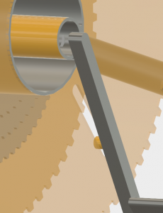
Two identically sized cogs are placed, one each, inside each pedal plane. They have a wide hollow bearing. The pedal bearings are inside the cog bearing, such that their axis of rotation of the pedals are behind that of the cogs. (Each pedal has its own bearing, although they share a common axis.) Each cog is propelled by a peg in its adjacent pedal, which extends into a slot in the cog, as shown here:
A pinion gear on the frame keeps the two cogs in sync:
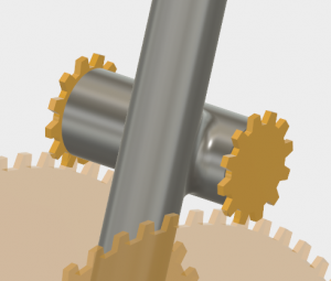
The right cog is connected directly to the three drive gears, which share the same hollow bearing. These are otherwise the same gears as is used in a traditional bike gear system.
The video below shows how the pin in the left pedal shaft propels the left cog via the slot in the cog.
Use cases…
This contraption might very well solve a non-existing problem. I’d be interested in your thoughts. One group that could benefit are those with missing or weak lower legs, where starting from a dead start, or going up hill, could be challenging when one pedal is directly above another with a traditional gearing system.
Version 2.0 ideas…
- Reduce the size of the two cogs, or better…
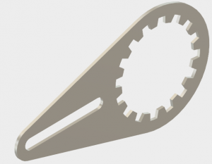
- Move the pinion to inside the large bearing cavity, and reshape the cogs thus:
Footnote: This project was mainly for the purpose of “cutting my teeth” on the Fusion 360 CAD package. It involved a few restarts and backtracking, both from being a F360 newbie and from figuring out what would and not work mechanically in the design. It was worth the effort. I now have a much better “feel” for how to proceed with modeling, and at the same time have a list of questions and recommendations for Autodesk and the F360 Forum. If interested in accounts of my future tinkerings, I humbly invite you to subscribe to the blog in the right side bar of the Home Page. Thanks!